The starting point was a working system but with nothing labelled, a very weak plastic fuse box and a ‘rat’s nest’ of wires. Also the Horn and Headlight fuse kept blowing (Didn’t understand why they have a common fuse) and the brake lights were not working.
So my primary tasks were to figure out the wiring diagram, what relays belonged to which, what fuses belonged to what and figure out why the horn fuse kept blowing.
Warning: These first phases are really a mind-clearing exercise for me, as well as a record of everything I figure out. As such it isn't very interesting !! But feel free to read it and if you happen to see anything I have missed or can suggest any answers to my questions, I would be grateful.
Here is a picture of the electrical panel:
So what we have here is:
1. A set of three Relays at the top (Let’s name them 1-3, No 3 is labelled 'Horn', No 2 is labelled ‘2’, the other is not labelled)
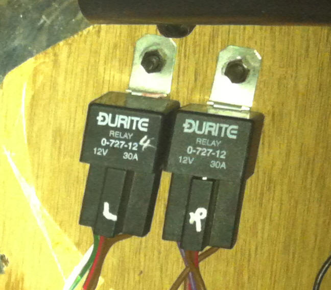
2. Two separate Relays on the left (labelled ‘L’&4 and ‘R’ (I think)). Let’s call them Relays 4 & 5
3. A 4-way box with 4 fuses (again one a bright yellow) (Call them 1-4)
4. A set of 6 in-line fuses, vertically mounted, and again one of is a bright yellow (Call them 5-10).
5. The ‘Flasher’ Relay
6. The ‘Kill Switch’
This is a close up of Relays 4 & 5, showing the labels. I have assumed they are ‘L’ & ‘R’, standing for ‘Left’ & ‘Right’ but maybe the mark is not ‘R’ but an ‘F’ (For Fuel) or ‘Omega’?
And maybe ‘L’ stands for Lamda ?
Have since found a software package that allows you to switch the fuel relay and this proved that Relay 5 is the Fuel Relay.
So far I haven’t found any more fuses or relays anywhere else in the car apart from one on the radiator that is for the cooling fan.
RELAYS
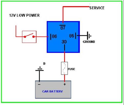
First I needed to remind myself the why & how of relays. A relay is designed to drive high-power services but switching using a low power circuit. This means that switches need only be rated for low current and, in particular high-powered currents do not pass through the ignition switch.
So Pin 30 always has a high-capacity 12V wire direct from the Battery, with a fuse.
Pin 87 (the one at right-angles to all the others) has a high-capacity wire going to the accessory which is then earthed on the other side.
Pin 85 has a low-capacity wire to Earth.
Pin 86 has a low-capacity wire leading to the switch which is driven by either a direct 12V supply or an ignition-switched 12V supply (For ‘live-switching’) if a service is ‘earth-switched’ the switch would not be there but Pin 85 would then go to a switch, and then to earth.
LOOM DIAGRAM
Then I looked at the Loom\Wiring diagram that came with the kit. This is not a normal wiring diagram, it simply shows you where to plug in each connector on the wiring loom, with a few extra 'hints' added.
This mentions 3 relays (Lamda Sensor, ECU and Fuel Pump). The Video that comes with the kit showed these as mounted on a single receptor and positioned to be installed inside the engine bay on the firewall (but I cannot see anything resembling this on the car).
It then has another relay, just pencilled in, for the Horn.
The details on the loom diagram given for wire colours are as follows:
ECU
Pin 30 No colour defined, just direct to Battery
Pin 85 White/Pink (Goes to ECU Pin 4)
Pin 86 No colour defined, just direct to Battery
Pin 87 Brown/Pink
(and also to Pin 86 Lamda Relay and ECU Pin 28)
Lamda Sensor Heater
Pin 30 No colour defined, just direct to Battery)
Pin 85 Black/Green (Goes to Pin 36 of ECU)
Pin 86 Brown/Pink (and also to Pin 87 ECU Relay)
Pin 87 Brown/Blue
Fuel Pump
Pin 30 No colour defined, just direct to Battery
Pin 85 Black/Purple (To ECU Pin 20)
Pin 86 No colour defined, just direct to Battery
Pin 87 No colour defined, just says Power to Fuel Pump
Horn
Pin 30 Brown (12V from Battery?)
Pin 85 Black
Pin 86 Purple/Black (from Horn Switch?)
Pin 87 No colour defined, just says Power to Horn
So this raises the first couple of ‘interesting’ observations:
1. The Fuel Pump is activated by the ECU not just the ignition. (Turns out the ECU runs the Fuel Pump for 2 seconds when you switch the ignition on, to prime the system)
2. The Lambda Sensor does not come on line until ECU is powered up (makes sense) (Turns out this relay controls the Lambda sensor Heater circuit, not the sensor itself. The ECU does not switch the heater on until the engine actually starts)
Now we can look at the wiring on the actual Relays
1
Pin 30
Brown/Red
Pin 85
Black
Pin 86
Brown/Red
Pin 87
Brown/Red
2
Pin 30
White/Pink
Pin 85
Green
Pin 86
White/Pink
Pin 87
Brown/Red
3
Pin 30
Brown
Pin 85
Black (x 2)
Pin 86
Purple/Black
Pin 87
Purple
4
Pin 30
Brown/Red
Pin 85
Green
Pin 86
Brown
Pin 87
White/Pink (x2)
5
Pin 30
Brown/Red
Pin 85
Purple
Pin 86
Fed from Pin 30
Pin 87
Brown/Red
All we get from that is that, apart from Relay 3 which exactly matches the wiring for the Horn (and was actually labelled ‘Horn’), the rest do not match up at all. Although Relay 5 does come close to the Fuel Pump. (Confirmed later)
I would also add that following ‘normal’ procedure I would have expected there would be relays for the following high-power circuits.
Headlights/Main, Headlights/Dip & Windscreen Demisters
So, the next stage was to remove each Relay in turn and try and figure out what stopped working.
Relay 1: This stopped the Windscreen Demisters.
Relay 2: This stopped the Fog Lights.
Relay 3: As we know, this is the Horn.
Relay 4 and Relay 5: Pulling either of these stopped the Fuel Pump so I could not start the car. (I now know that Relay 4 is the Fuel Pump itself, and that Relay 5 is the Lambda Sensor Heater Relay)
I should add that I have no idea what the effect is of removing the ECU and Lamda Sensor Relays would be on the engine. Logic tells me that removing the Lamda Sensor Replay would have little effect as it controls the mixture so the engine would probably still start, maybe running badly. Removing the ECU Relay should stop the engine from starting as the Fuel Pump is not activated?
So this leads to the following observations:
1. Relays 1-3 do not appear on the Wiring Diagram (except the horn which is hand drawn in)
2. So we now have 3 Relays to find (ECU/Lamda/Fuel Pump) and only 2 (4 & 5, ‘L’ & ‘R’) on the panel
4. (Lambda Sensor Heater & Fuel Pump identified, no sign of Main ECU relay)
3. There do not appear to be relays for the Headlights? (I have been told that there are no Headlamp replays. Seems odd as it means the whole current passes through the light switch?)
Status: Just need to track down the ECU Relay. I can hear it clicking behind dash and instrument cluster.


No comments:
Post a Comment