Now that the summer is finished and the weather is getting poor the big decision for all kit car owners comes around. Should you take the car off the road and do all those jobs that have been stacking up over the summer. Or do you brave the cold weather and continue to drive the car over the winter.
My decision: Keep her running and just wrap up warmly.
SuperSpec

Saturday, 30 November 2013
Wednesday, 27 November 2013
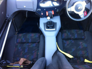
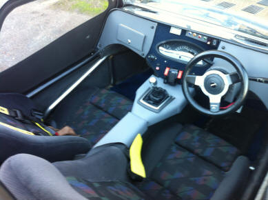
Dashboard Project - Phase Four
The next stage was covering the gear lever housing and transmission tunnel in vinyl to match, and I took the opportunity to fit a nice chrome surrounded gear lever mounting of a Ford Fiesta.
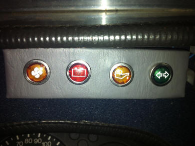 For my birthday I treated myself to a new set of warning lights that actually have the correct symbols displayed. So far they are: Cooling fan, Alternator, Oil Pressure and Indicators. I have also got ones for Headlight Full Beam and Handbrake Warning, which are still to be fitted.
Status: - Getting there slowly, just centre console left.
Status: - Getting there slowly, just centre console left.
Saturday, 23 November 2013
Battery Isolation Switch
I got sick and tired of disconnecting/reconnecting the battery while I was testing the electrics so I fitted a Battery isolation switch.
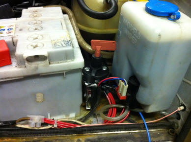 For those that don't know, if you remove that red key the car is then completely dead electrically and will not start. It's official purpose is to make it more difficult to steal so that might come in useful if I ever have to leave it somewhere.
Although you can buy those keys for £1.50 off E-Bay so I guess a professional thief would carry one around with him,
But it would deter the casual thief and stop those people who think it is clever to reach in and turn on the hazard warning lights to drain the battery.
Status: Complete
Although you can buy those keys for £1.50 off E-Bay so I guess a professional thief would carry one around with him,
But it would deter the casual thief and stop those people who think it is clever to reach in and turn on the hazard warning lights to drain the battery.
Status: Complete
Saturday, 16 November 2013
The Starting Problem
There are a few thoughts on why the engine struggles to crank when you try and start a hot engine:
1. The engine itself ‘tightens’ up when it is warm, making it difficult to turn over.
2. Advice on the forum is that the absence of a decent earth strap from engine to chassis can cause a voltage drop.
3. If the ignition advance is too much it would make it difficult to turn over.
There is nothing I can about (1), and (3) is controlled by the ECU, so all I can do is fit a proper earth strap and hope it helps.
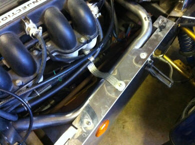 Here it is:
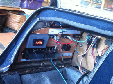 I also decided to add a voltmeter into the circuit so I could see if the battery was struggling. I didn't want it to be a permanent distraction so mounted it on the auxiliary electrical panel where it can easily be viewed when troubleshooting.
As you can see, at 12.5V it is quite healthy. When the ignition is switched on it drops to 12.3V, which is fair. If you turn on a high-power system like the demisters or the headlights then it drops to 11.8V, not unexpected. Once the engine is running it shows 14.1V which means the alternator is charging it well.
The only slight concern is that while cranking it initially drops to 9V before recovering to 9.8V. That is marginal. Something to keep an eye on.
Update: March 2014 - Now had a chance to try a hot start and everything was fine. See "Sunday Run with Hot Start"
Status: Complete
1. The engine itself ‘tightens’ up when it is warm, making it difficult to turn over.
2. Advice on the forum is that the absence of a decent earth strap from engine to chassis can cause a voltage drop.
3. If the ignition advance is too much it would make it difficult to turn over.
There is nothing I can about (1), and (3) is controlled by the ECU, so all I can do is fit a proper earth strap and hope it helps.
As you can see, at 12.5V it is quite healthy. When the ignition is switched on it drops to 12.3V, which is fair. If you turn on a high-power system like the demisters or the headlights then it drops to 11.8V, not unexpected. Once the engine is running it shows 14.1V which means the alternator is charging it well.
The only slight concern is that while cranking it initially drops to 9V before recovering to 9.8V. That is marginal. Something to keep an eye on.
Update: March 2014 - Now had a chance to try a hot start and everything was fine. See "Sunday Run with Hot Start"
Status: Complete
Tuesday, 12 November 2013
The 'Electrics' Project - Services
The next stage was a list of all the electrical
‘services’, annotated as to whether they used a ‘direct’ 12V supply or an
ignition switched 12V, whether they ought to use a Relay (and if so which one),
and which fuse they used.
(Red is unknown)
Instrument Panel Wiring
The 2 White wires are interchangeable
Light Switch gets Direct Power from Fuse 1.
Pins 86 get fed an ignition switched earth feed (Apparently not, seems to be permanent earth?)
1. Where is the relay for the Lamda Sensor Heater ?
(Red is unknown)
Service
|
12V
|
Colour
|
Relay
|
Fuse
|
Demisters
|
Ignition
|
Yes – Relay 1
|
3
|
|
Fog Lights
|
Direct
|
Blue/Yellow
|
Yes – Relay 2
|
4
|
Horn
|
Direct
|
Purple/Black
|
Yes – Relay 3
|
1
|
Headlights (Main)
|
Direct
|
Blue/Red
|
Apparently none
|
1
|
Headlights (Dipped)
|
Direct
|
Blue/White
|
Apparently none |
1
|
Cooling Fan
|
Direct
|
???
|
Yes - Relay at Front
|
11 |
ECU
|
Ignition
|
Green/Pink
|
Yes - Not found
|
?
|
Lamda Sensor
|
Ignition
|
Green
|
Yes - Relay 4
|
?
|
Fuel Pump
|
Ignition
|
White
|
Yes - Relay 5
|
?
|
Indicators
|
Ignition
|
Green/White
|
Yes – Flasher Relay
|
?
|
Hazards
|
Direct
|
Green/White
|
Yes – Flasher Relay
|
?
|
Sidelights
|
Direct
|
Red
|
No
|
4
|
Number Plate Light
|
Direct
|
Red
|
No
|
4
|
Reversing Lights
|
Direct
|
???
|
No
|
10
|
Brake Lights
|
Ignition
|
Green/Purple
|
No
|
4
|
Cluster Illumination
|
Ignition
|
Red
|
No
|
4
|
Instruments
|
Ignition
|
Green
|
No
|
2
|
Warning Lights
|
Ignition
|
Green
|
No
|
2
|
Wipers
|
Ignition
|
Blue/Yellow
|
No
|
?
|
Washers
|
Ignition
|
Green/Black
|
No
|
?
|
Just for completeness I figured out the Instrument Panel
wiring: (Blue means Not used, Red means don’t know)
Pin
|
Colour
|
Usage
|
White Plug
|
||
12
|
Red
|
+12V for Panel illumination
|
11
|
Blue/White
|
Headlight Full Beam Warning
|
10
|
Black
|
Earth for Headlamp Warning and Panel Illumination
|
9
|
Not Used
|
(ABS warning light)
|
8
|
Black/Yellow
|
Handbrake/Brake
Fluid Level Warning Light
|
7
|
White/Green
|
‘S’ Connector on Temperature Gauge (Sender)
|
6
|
White
|
‘S’ Connector on Fuel Gauge (Sender)
|
5
|
Black
|
‘E’ (Earth) (Earth) for Fuel and Temperature Gauge
|
4
|
Not Used
|
(Diesel GlowPlug)
|
3
|
Not Used
|
(Washer Fluid Level)
|
2
|
Not Used
|
(Low Fuel)
|
1
|
Green
|
12V for lamps and ‘B+’ on Fuel & Temperature
|
Blue
Plug
|
||
1
|
Black
|
Earth for Indicator Lights
|
2
|
????*
|
Indicator Lights
|
3
|
Not Used
|
(Windows ??)
|
4
|
Not Used
|
(?????)
|
5
|
Not Used
|
(Seat Belt)
|
6
|
?????*
|
From Negative Side of Coil
(not connected on board ?)**
|
7
|
Brown/Yellow
|
Alternator Warning Light
|
8
|
?????*
|
‘E’ on Tachometer (from +ve side of coil)
|
9
|
?????*
|
‘S’ on Tachometer
|
10
|
White/Brown
|
Oil Pressure Warning
|
11
|
Not Used
|
(Rear Screen Heater)
|
12
|
Green
|
‘B’ on Tacho (12V ignition switched)
|
* I will be able to
complete the colour column when I remove the centre dashboard.
** The
wiring diagram says to connect to coil but on PCB on back of cluster it doesn’t
appear to be connected to anything.
LAMDA
SENSOR
Not something I have seen before so needed to figure out
the wiring. Seems it is:
Sensor
|
Engine
Plug
|
Function
|
White*
|
Black
(Earth)
|
Heater
|
White*
|
Brown/Blue (Power)
|
Heater
|
Grey
|
Green
|
Signal
|
Black
|
Grey
|
Earth
|
The 2 White wires are interchangeable
ECU
The Electronic Control Unit is a ‘black box’, but I did
find a breakdown of the connections:
Pin
|
Colour
|
Function or Termination
|
Comments
|
1
|
White/Yellow
|
Coil -ve
|
Not Used
|
2
|
Pink/Blue
|
Stepper Motor Phase 2
|
|
3
|
Orange/Grey
|
Stepper Motor Phase 1
|
|
4
|
White/Pink
|
Feed from main ECU relay
|
-ve side of Switching Circuit
|
5
|
Not Used
|
Air Con Control
|
|
6
|
Not Used
|
Cooling Fan Relay
|
|
7
|
Grey
|
Lambda sensor +
|
Revised wiring extension
|
8
|
Yellow/Green
|
Throttle Sensor Supply
|
|
9
|
Yellow/Purple
|
Throttle Sensor Input
|
|
10
|
Pink
|
Diagnostics Output
|
|
11
|
Green/Pink
|
Ignition Sensing
|
|
12
|
Not Used
|
Electronic Tacho Output
|
|
13
|
Black/White
|
Immobiliser Control
|
Disabled
|
14
|
Not Used
|
??
|
|
15
|
Not Used
|
Air Con Control
|
|
16
|
Green/Black
|
Air Temp Sensor Input
|
|
17
|
Yellow
|
Engine Knock Sensor
|
|
18
|
Light Green
|
Lambda sensor -
|
|
19
|
Not Used
|
Air Con Control
|
|
20
|
Black/Purple
|
Fuel Cut off Relay Control.
|
-ve side of Switching Circuit
|
21
|
Yellow/Orange
|
Boost Purge Valve
|
|
22
|
Orange/Green
|
Stepper Motor Phase 3
|
|
23
|
Yellow/Green
|
Injector 1-4
|
|
24
|
Yellow/Blue
|
Injector 2-3
|
|
25
|
White/Black
|
Coil +
|
Actually to Coil -ve
|
26
|
Not Used
|
Cruise Control
|
|
27
|
Orange/Blue
|
Stepper Motor Phase 4
|
|
28
|
Brown/Pink
|
+12V Power
|
+ve Power circuit from Relay
|
29
|
Black
|
ECU Earth
|
|
30
|
Pink/Black
|
Engine Sensors Earth
|
|
31
|
Blue
|
Crankshaft Sensor +
|
|
32
|
White
|
Crankshaft Sensor -
|
|
33
|
Pink/Green
|
Coolant Sensor Input
|
|
34
|
Grey/Pink
|
Fuel Rail Sensor Input
|
|
35
|
Not Used
|
Air Con Control
|
|
36
|
Black/Green
|
Lambda Sensor
|
-ve side of Switching Circuit
|
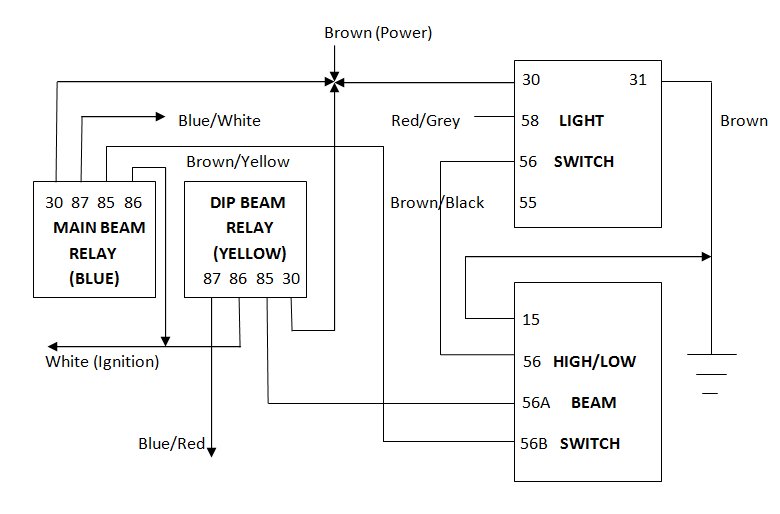
LIGHTING
CIRCUIT
Pin 30 on both relays get a permanent +12 V Power Supply
from Fuse 1
Pin 87 on the relays goes to Main Beam (Blue/White) and
Dipped Beam (Blue/Red)
Light Switch gets Direct Power from Fuse 1.
Position 1 sends power to
sidelights through (Red/Grey)
Position 2 sends power to High/Dip
Switch which feeds Pin 85 of appropriate relay
Pins 86 get fed an ignition switched earth feed (Apparently not, seems to be permanent earth?)
Status: Lots to do, I still have the following outstanding questions
1. Where is the relay for the Lamda Sensor Heater ?
2. What are Fuses 5-9 for ?
3. Where are the fuses for the indicators and wipers/washers ?
3. Where are the fuses for the indicators and wipers/washers ?
Subscribe to:
Comments (Atom)