SuperSpec

SuperSpec

Thursday 26 September 2013

Wheel Alignment

Following the ride height adjustment and bearing in mind the squeal on left corners I decided to check the steering alignment (Camber and Tracking, the Castor is fixed by the design of the kit). 

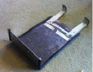
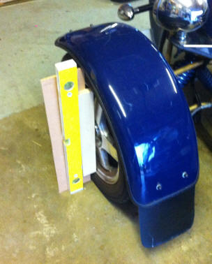
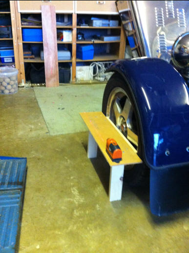
To do this I designed and built an alignment tool out of scrap timber, mating it with a spirit level for the camber and a laser pointer for the tracking. 

Here it is checking the camber. This gave results of -1.1° for the offside and +0.4° for the nearside. There are no laid down standards for kit cars but as a general rule they should be between 0° to -1.5° (A negative figure shows the top leaning into the car). So in an ideal world I ought to tweak the offside about a degree. Unfortunately it isn’t a simple adjustment, the suspension needs to be taken apart. Meanwhile it is OK for normal use, just might wear the tires a bit. 

And here it is checking the tracking. The wooden stand has 2 nails in it, one at each end, EXACTLY equal in distance from the wheel rim. So by putting the centre point of the laser on one nail and ensuring the laser light illuminates the other nail we know the beam is parallel to the wheel. The picture shows the laser beam illuminating on the back of the garage wall, and by moving the laser to the other end of the wood and facing the other way the beam illuminates on the garage door. Then swap over to the other wheel and repeat the exercise. Then measure the gap between the beams on the wall (XWall) and the door (XDoor) and knowing the length of the garage (LG) then you can work out the tracking using the formula:

 Tan-1 ( (XDoor – XWall) / LG) 

I was quite pleased to get a result of -0.826° (Toe-in). Again there are no official settings but most people advise a ‘touch’ of toe-in so that looks fine. I also did the rears and came up with -0.418°, again well within limits.

Status: Complete

Saturday 21 September 2013

Dashboard Project - Phase Two

The electrical panel was above the passenger footwell and almost impossible to reach, so the first step was to rebuild the passenger side of the dashboard to allow access, and to replace it with a vinyl-covered quick removable panel.  I also incorporated a lockable glove box to keep the vehicle documents, iPhone Charger, boot key and a woolly hat.


Status:  Phase 2 complete, more to do


Saturday 14 September 2013

The Sump Guard

Although I now had a decent ground clearance, just to be really safe I also manufactured a sump guard from some scrap sheet metal so if I do ground it will be this that hits rather than the sump. It reduced the ground clearance a bit but only by about 4mm. (First go at pop riveting, very successful) 


Before:

After:


Status:  Complete

Wednesday 4 September 2013

Ride Height Adjustment

Again I did a lot of research into this and asked other owners.   The most common answer was to replace the shock absorbers as this was one area where going for the cheapest option had resulted in a very poor ride.  But that is going to cost over £300 so I have that on the ‘future’ list.

It’s difficult to tell from the picture but the bottom mounting is on the 3rd of 4 holes on the wishbone so it seemed obvious that moving it to a hole nearer the chassis would raise the ride height.  


Unfortunately the advice was that this would put excessive stress on the wishbone and risk bending it if I hit a pothole. 

So the next thing to try was to wind the coil spring up.  You can tell from the picture that it was fully extended. 
 

After buying the right tool off E-Bay I wound the coils up about 11 turns as shown.   This raised the ride height from the 2” clearance below the sump to about 3.5”.  doesn’t  sound a lot but it had a dramatic improvement on the ‘grounding’ and I haven’t done it since.


However, I did find the steering became a light above 60mph, so after a few weeks I wound then back down 2 turns.   I still had 3” sump clearance and the handling seemed better.